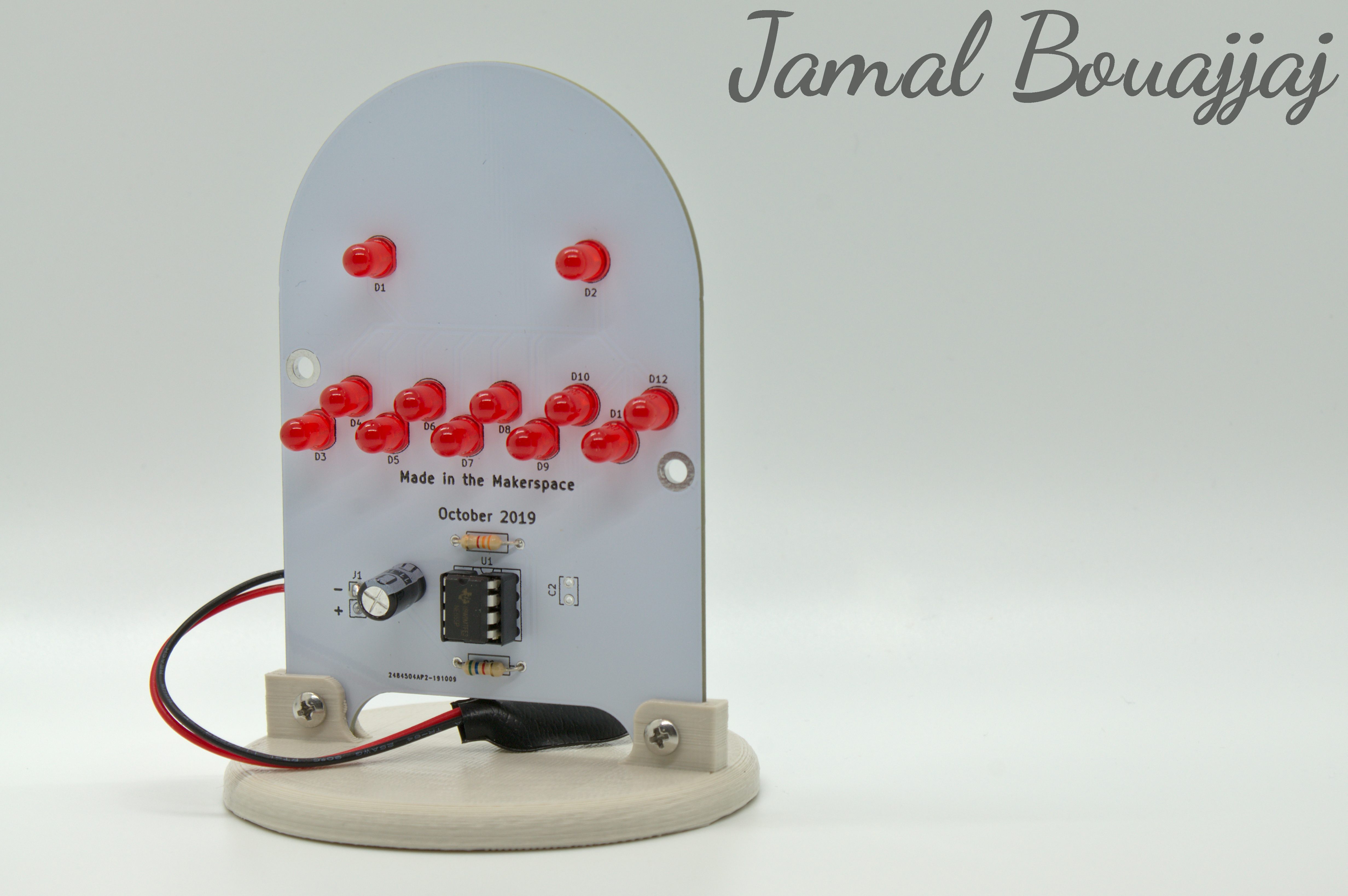
This project is a PCB soldering kit in the shape of a ghost. The kit has been designed with some SMD and THT parts. If you plan to use this design as a kit for people who have no/minimal soldering experience, it is recommended to pre-solder the SMD parts before giving the board to them for them to solder.
Click the GitHub folder below to access the project's files, which include the KiCad PCB files, the Gerber files, and the Autodesk Inventor CAD files.
This kit has some THT and SMD parts to be soldered (THT means through-hole, and SMD means surface-mount).
| PCB Reference | Part Description | Package Size | Quantity per Board |
| R1 | 5.6kΩ Resistor | THT | 1 |
| R2 | 3.3kΩ Resistor | THT | 1 |
| U1 | 555 Timer | DPI-8 | 1 |
| C1 | 100uF Capacitor | THT | 1 |
| C2 (Optional) | 0.1uF Capacitor | THT | 1 |
| C3 (Optiona) | 0.1uF Capacitor | SMD-1206 | 1 |
| D1-D12 | 5mm LED | THT | 12 |
| R3-R14 | 270Ω Resistor | SMD-1206 | 12 |
| J1 | 9v Harness | Wire | 1 |
The circuit is based on the 555 timer. The chip, if set up as done in this circuit, will act as an oscillator, which will generate a square wave on the output, in which the frequency is dependent on R1, R2, and C1. With the chosen values, the output will have a frequency of 1.2Hz, also meaning the output will oscillate once every 0.85 seconds. This output is used to drive the 12 LEDs on the board directly.
Here is the PCB's schematic:

Here is some diagrams relating to the project:


I have designed a base for the ghost to sit on.
The files for the cover and base can be found in the project's folder