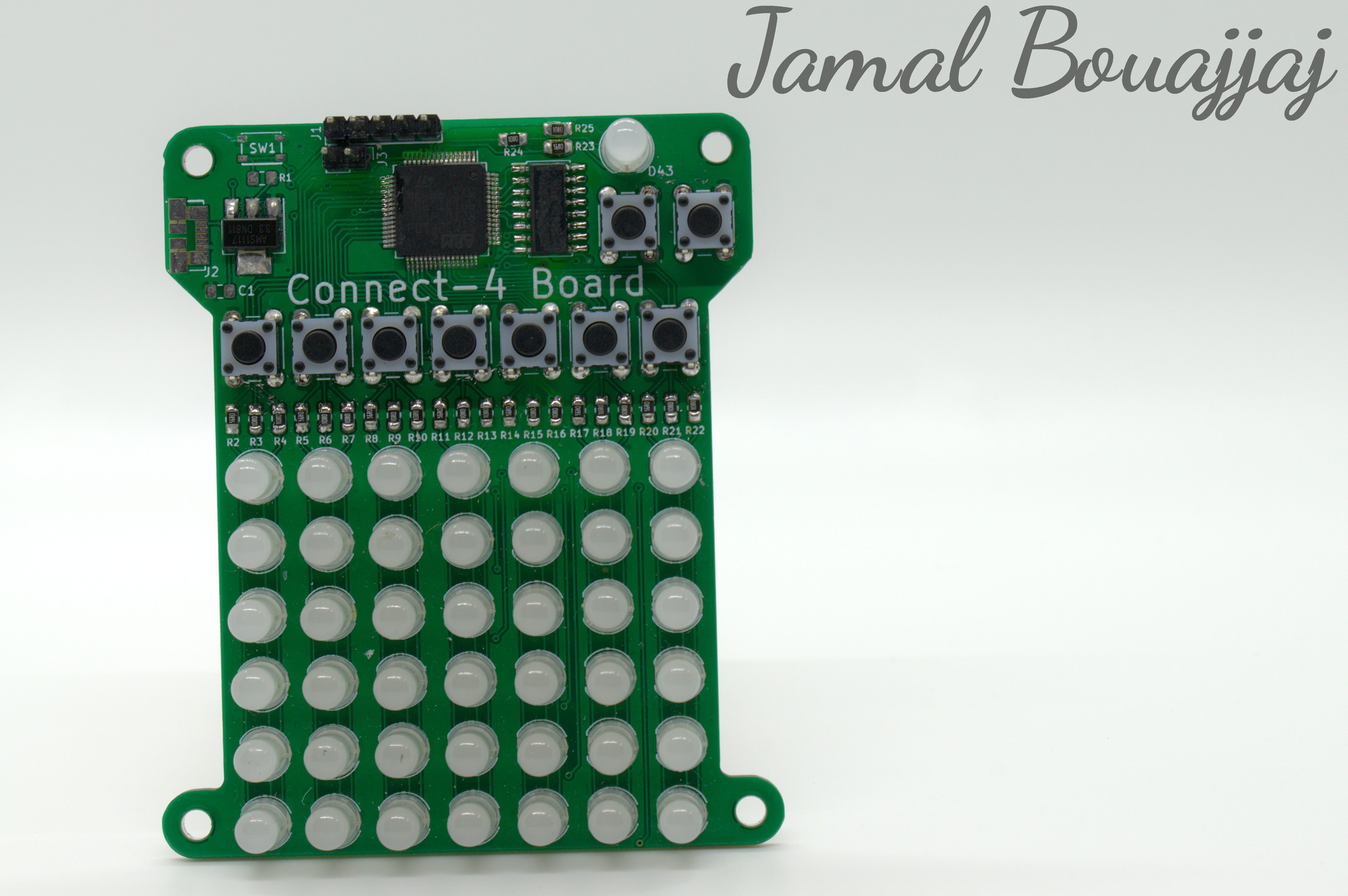
This project is a Connect 4 game designed in a circuit board. There is a 7x6 LED matrix for the "board" of the game. Each column has a button right on top of it, simulating dropping a disk in a column. There is another LED and 2 buttons for other purposes, such as restarting the game and indicating who's turn is it.
Click the GitHub folder below to access the project's files, which include the KiCad PCB files, the Gerber files, and the Autodesk Inventor CAD files.
Here are the parts you will need to solder this project
SW1 and R1 are completely optional, as they are used for the in-board reset button for the ST microcontroller
| PCB Reference | Part Description/Values | Package Size | Quantity per Board |
| C1 | Decoupling Cap (0.1 -> 10uF) | 0805 | 1 |
| D1-D43 | 5mm RGB LED | 5mm | 43 |
| J1 | Programming Header | 5-pin 0.1" male header | 1 |
| J2 | USB Micro | Molex 47346 | 1 |
| J3 | Power | 2-pin 0.1" header or Wire | 1 |
| R1 | 1kΩ Resistor | 0805 | 1 |
| R2-R25 | Resistors | 100Ω for Red, 56Ω for Green and Blue | 0805 | 24 |
| SW1 | Minature Tactile Switch | PTS810 | 1 |
| SW2-SW10 | Tactile Switches | 4-pin 6mm tactile switch | 9 |
| U1 | AMS1117-3.3 Voltage Regulator | SOT-223-3 | 1 |
| U2 | ULN2003 Darlington Array | SOP-16 | 1 |
| U3 | STM32F103RCTx | LQFP-64 | 1 |
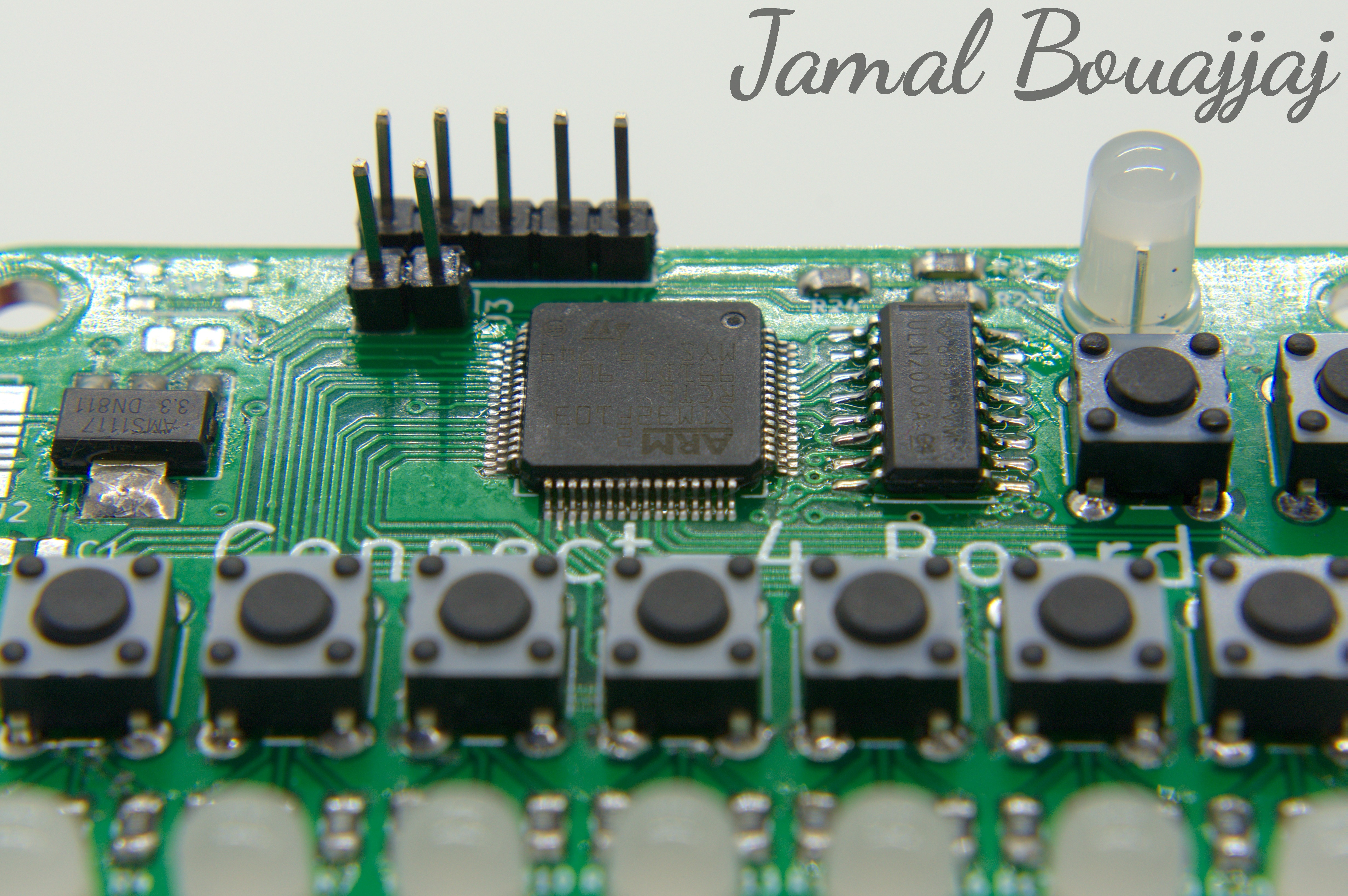
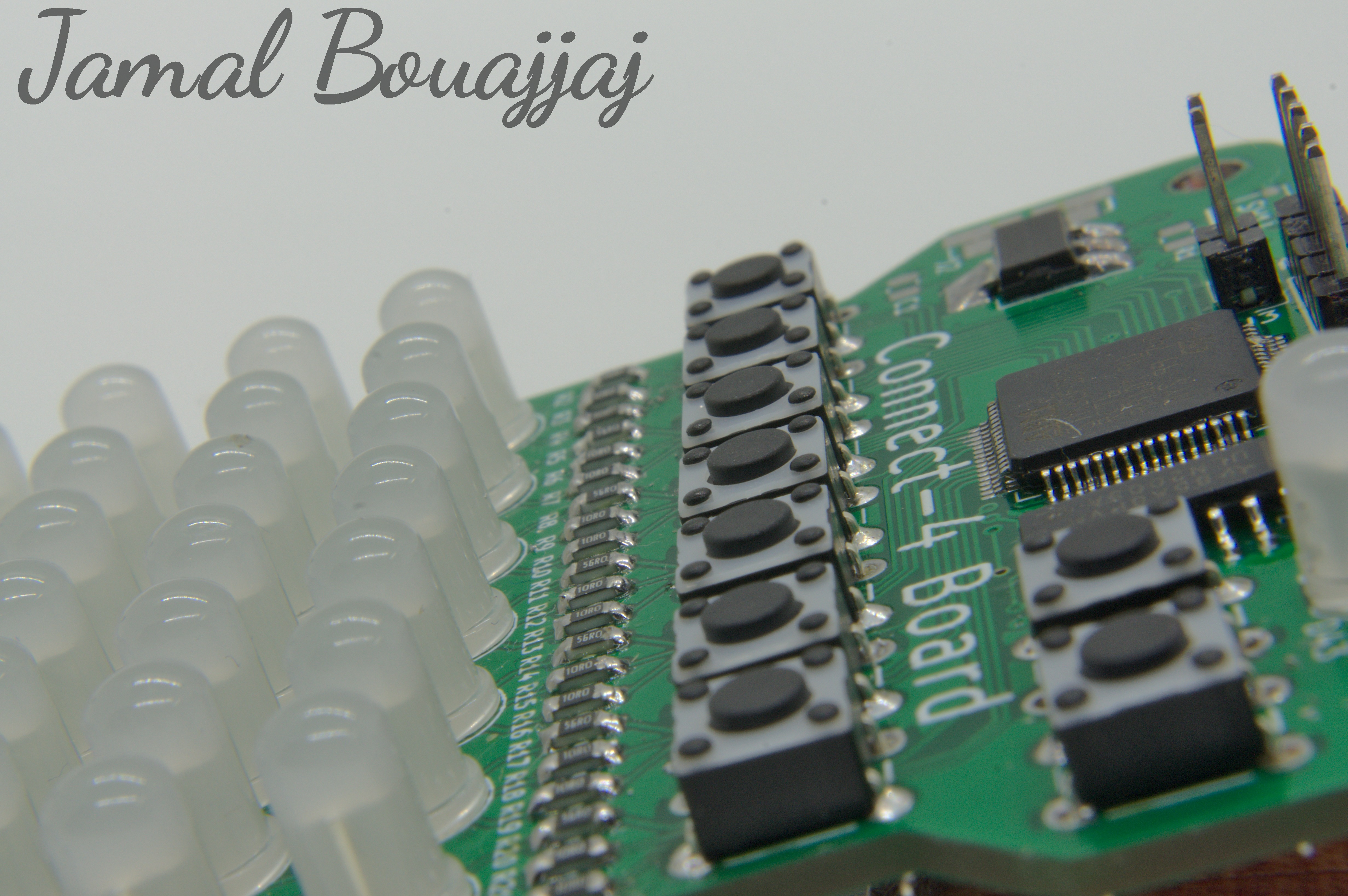
The circuit is based on an STM32F103 microcontroller. The microcontroller directly drives all LED individually by supplying power to their anodes. There is a Darlington array IC (ULN2003) which pull all LED's cathodes in a row to GND. The ULN2003 is also controlled by the microcontroller. This setup results in the game's LED matrix capable of being multiplexed to display any combination on the matrix while reducing power consumption. Other than that, there is a USB input connector, an optional reset switch for the microcontroller, a programming header, and a 3.3V regulator.
The complexity of the project mainly arises in the software. The software is programmed in the AC6 Workbench for STM32 environment. When the board is initialized, the STM32 starts by initializing the GPIO peripherals to set each pin to an input or output depending on what that pin is hooked up to. Then, Timer 7 is initialized to trigger every 1ms. When triggered, the timer will interrupt the program to a function titled "TIM6_IRQHandler", which drives the matrix's LEDs depending on the value of a global LED array which stores which colors on each LED of the matrix that will be lit-up. The LEDs are multiplexed, so the function cycles thru all rows one at a time. There is another array, called "players", that stores the "chips" on the board and who "placed" each one. There is functional called "playerToLed" that converts the information in this array to the global LED array to be displayed. This function is called upon during the game's loop when it wants to update the display. During the main game loop, when Timer 7 has not interrupted the program, the loop waits for one of the buttons to be pressed. When pressed, if the button is the left-most button at the top of the PCB, the game will reset itself. If the button pressed is one of the columns, it will find the row that isn't occupied by another "chip". Once found, it stores the player's ID (1 or 2) into the mentioned "players" array. The game then checks if there is a winner by the "checkForWinner" function, which checks the "players" array for 4 "chips" dropped by the same player 4 times in a row diagonally, horizontally, and vertically. If there is a winner, the game will stop and indicate which one. If both cases where there is a player or the game was manually reset, the right-most button on the top of the PCB(right below the indicator LED) can be pressed to restart the game loop.
Here is the PCB's schematic:

Comming Soon!
The PCB has 4 M3 mounting holes to be screwed on to a case. I have designed a case for this board in Fusion360. The STEP and STL files will be released soon in the page's GitHub repository.
The PCB is designed to be programed by using the pin headers at the top of the board (J1). The pinout for the connector can be found in the schematic. You could use any STM32 programmer, including the popular ST-Link 2, to program the board.
The programming software used (AC6 for STM32 Workbench) can be found here!